|
|

|
|
| Partname: | 142-0701-851 |
| Description: | Evaluation Board Manual for High Frequency LQFP32 |
| Manufacturer: | ON Semiconductor |
| Datasheet: | PDF (238K).
Click here to download *) |
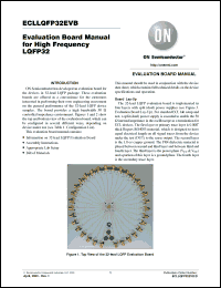
The 32-lead LQFP evaluation board is implemented in four layers with split (dual) power supplies (see Figure 3. Evaluation Board Lay-Up). For standard ECL lab setup and test, a split (dual) power supply is essential to enable the 50 W internal impedance in the oscilloscope as a termination for ECL devices. The first layer or primary trace layer is 0.008 thick Rogers RO4003 material, which is designed to have equal electrical length on all signal traces from the device under the test (DUT) to the sense output. The second layer is the 1.0 oz copper ground. The FR4 dielectric material is placed between second and third layer and between third and fourth layer. The third layer is the power plane (VCC & VEE) and a portion of this layer is a ground plane. The fourth layer is the secondary trace layer. |
|

Click here to download 142-0701-851 Datasheet*) |
 |
| *)Datasheets downloading from ChipDocs is only for our members (paid service). REGISTER NOW for your membership. |
|
|
|

